Sensors with ARTIK IDE
ARTIK modules provide connection capability for analog inputs and various digital inputs and outputs, as well as I2C, UART, and SPI connections. The ARTIK 05X starter board includes headers with an Arduino-friendly layout that lets you easily add readily available sensors as we show below.
Here we specifically refer to the Sensor app SystemIO code that comes with the ARTIK IDE, or to the similar sensorbd_demo code cross-compiled from Linux.
Grove Base Shield
The Grove Base Shield and sensors in this article are compatible with the ARTIK 05X starter kit board. You use C language example code to read these sensors.

To get started, take a look at the Sensor Board sample application code provided. It's pretty straightforward code so you'll figure out quickly how to modify it to suit your needs.
Analog
| Temperature Sensor | UV Sensor | Moisture Sensor | Light Sensor | Rotary Angle Sensor | Luminance Sensor |
 |
 |
 |
 |
 |
 |
The command below prints out analog sensor reading from channel 1-4. These four channels match the A0-A3 analog pins on the Grove Base shield.
The first thing you'll want to do is add a delay between loops such as sleep(1); so that you can see the results.
sensor adctest
nsamples=4
Sample:
1: channel: 3, value: 14
2: channel: 0, value: 1963
3: channel: 1, value: 85
4: channel: 3, value: 16
nsamples=4
Sample:
1: channel: 0, value: 1962
2: channel: 1, value: 84
3: channel: 2, value: 5
4: channel: 2, value: 7
nsamples=4
Sample:
1: channel: 3, value: 17
2: channel: 0, value: 1962
3: channel: 1, value: 85
4: channel: 1, value: 85
You can change the source code here to only listen for selected channels.
I2C
| MPU9250 Accelerometer |
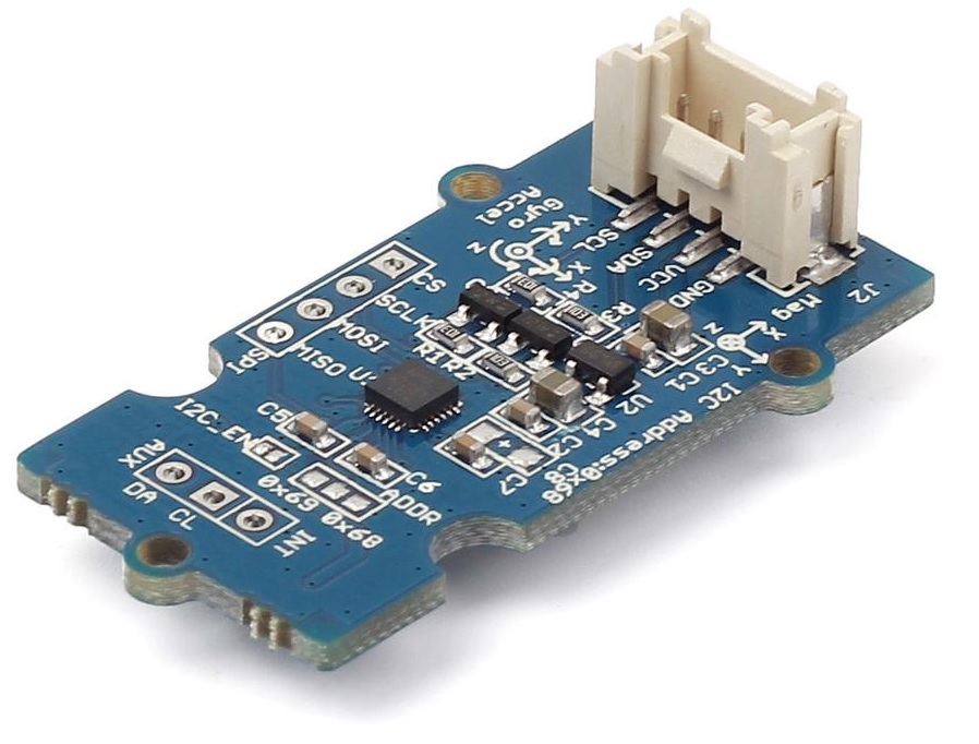 |
MPU9250 I2C accelerometer support has been integrated in the ARTIK 05X code base. By using sensor sample code, you can read the accelerometer XYZ raw data, and calculate Euler angles by using the data.
If you read through i2c_mpu9250.c, you can find in the mpu9250_main() function that the code sets the default I2C port number to be 1, which refers to the SCL/SDA pins on header CON703. Changing the default port number to 0 will enable the I2C pins on header CON708.
Attach a Grove IMU 9DOF V2.0 motion tracking module to the I2C connector next to D8 on your base shield, and you can read accelerometer raw data by using the command below.
sensor mpu9250
ACC:      X         Y         Z
ACC:      -10796    280       17092
readbytes:
readbytes: 1
readbytes:
readbytes: 2
readbytes:
readbytes: 1
readbytes:
readbytes: 2
readbytes:
readbytes: 1
readbytes:
readbytes: 2
ACC:      476       292       17120
readbytes:
readbytes: 1
readbytes:
readbytes: 2
readbytes:
readbytes: 1
readbytes:
readbytes: 2
readbytes:
readbytes: 1
readbytes:
readbytes: 2
ACC:      512       260       17028
…
You will find a related article on the I2C interface that includes a new ARTIK IDE project to teach the fundamentals of I2C programming on Tizen RT.
Digital
| Grove LED Socket Kit |
 |
Digital pins can be operated via the sensor example as well. Here are some of the mappings for these pins.
ARD pin 2 – gpio 46
ARD pin 4 – gpio 47
ARD pin 7 – gpio 48
ARD pin 8 – gpio 50
The command below can pull the readings from a specific GPIO pin.
sensor gpio
PWM
You'll find several pulse width modulator (PWM) circuit output pins that can be tested with an external buzzer circuit using this command.
sensor pwm