Programming the I2C Interface
I2C Master
We make use of the MPU9250 device to obtain accelerometer values on all 3 axes, and calculate roll and pitch using a low-pass filter to determine the direction of the tilt.
Our project uses I2C as the communication interface between the ARTIK 05x and the MPU9250 component, and employs the on-board LEDs to indicate the direction of the tilt.
Prerequisites
You'll be using an ARTIK 053 or 055 development board and the ARTIK IDE, along with the MPU9250 device mounted on a Grove shield as shown in the Sensors article. It is more easily used with the base shield described in that article, although you can also wire it by hand directly to your ARTIK board.
| MPU9250 Accelerometer |
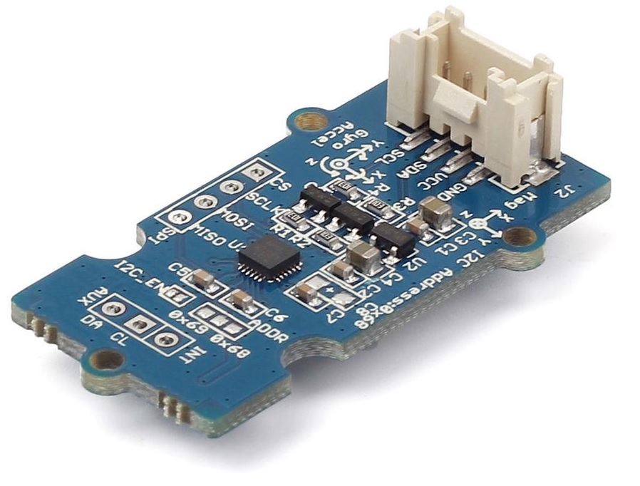 |
You'll need to determine the I2C pins you plan to use. Look at the mappings page, as well as the Tizen RT source code files noted there.
| I2C name | Connector location |
|---|---|
| XI2C0 pins | Arduino-friendly interface |
| XI2C1 pins | CON703 pins 8 and 10 |
Set up sensor code
You will use an ARTIK 05X module as your edge device and create a project in the ARTIK IDE.
- In the ARTIK v2.0 IDE, create a new ARTIK 05X C Project. Name the project anything you like. Click Next.
- Select the Hello World example, which we'll just use as a placeholder for our code. Click Next.
- You'll just use the default settings on the Configuration page, as 'typical' already has the needed I2C components. Click Next, then Finish.
- Delete the "hello_main.c" file in Project Explorer.
-
Download the file bundle containing the main.c code
and
i2c_mpu9250.hheader file for the sensor itself. - Extract the main.c and mpu9250.h files, then drag the two files from the extracted folder into Project Explorer onto the name of your project.
-
Edit main.c to change the name of the
mainfunction tohello_mainso that you end up with:
int
hello_main(int argc, char *argv[]) { . . . - Build the code as usual.
- Flash-load the code to your ARTIK 05X board as always.
You're ready to go!
hello_main.c is the name is used in the hidden _main.c file that adds your program to the TASH menu. Modify that file to suit your application.
Run sensor code
Start by connecting your sensor to your chosen I2C port on the ARTIK 05X board, either wiring it directly or using a base shield board and plugging into any of the Arduino I2C connectors.
Note: If using a base shield to connect your sensor, make sure you set its switch to 3.3V.
Any time you apply power or hit reset, your board will go straight into program operation.
– Start by holding the sensor board flat on your work surface.
– Tilt the board on its long edge: The BLUE LED lights.
– Tilt the board on its short edge: The RED LED lights.
You can see the exact sensor values on the console.
Follow the flow
When you hit reset, the code executes these basic functions. Click to see specific code samples.
-
Set up the I2C port
static struct i2c_dev_s *i2c_dev;
static struct i2c_config_s configs_1;
-
Initialize the device details structure with the port of I2C - 0 in this case
(If using the I2C ports on CON 703, use 1).int port = 0; i2c_dev = up_i2cinitialize(port); if (i2c_dev == NULL) { printf("i2ctest_main: up_i2cinitialize(i2c:%d) failed\n", port); goto errout; } configs_1.frequency = 40000; configs_1.address = MPU9250_ADDR; configs_1.addrlen = 7; -
Read raw MPU9250 sensor data, using the “mpu9250_get_axis(..)” function to read the raw sensor values from MPU9250.
uint16_t data_2[3]; while(true) { data_2[0] = 0; data_2[1] = 0; data_2[2] = 0; if (mpu9250_get_axis(&data_2[0], &data_2[1], &data_2[2]) != 0) { printf("get error!\n"); } else { calculate((int16_t)data_2[0], (int16_t)data_2[1], (int16_t)data_2[2]); printf("ACC: %-10d%-10d%-10d\n", (int16_t)data_2[0], (int16_t)data_2[1], (int16_t)data_2[2]); printf("Pitch - %f, Roll - %f\n", pitch, roll); } The following are read from MPU9250 – Accelerometer reading in all 3 axes uint8_t mpu9250_accel_out[3] = { MPU9250_ACCEL_XOUT_H, MPU9250_ACCEL_YOUT_H, MPU9250_ACCEL_ZOUT_H, }; static int mpu9250_get_axis(uint16_t *x, uint16_t *y, uint16_t *z) { int i; int ret = OK; uint8_t reg; uint8_t data[6]; for (i = 0; i < 6; i++) { data[i] = 0; } reg = mpu9250_accel_out[MPU9250_AXIS_X]; ret = i2c_write(i2c_dev, &configs_1, ®, 1); if (ret < 0) { printf("i2c_write fail(%d)\n", ret); return -ret; } up_mdelay(1); ret = i2c_read(i2c_dev, &configs_1, data, 6); if (ret < 0) { printf("i2c_read fail(%d)\n", ret); return -ret; } *x = (data[0] << 8) | data[1]; *y = (data[2] << 8) | data[3]; *z = (data[4] << 8) | data[5]; return OK; } -
Calculate pitch and roll (using a low-pass filter)
void calculate(int x, int y, int z) { //Low Pass Filter fXg = (double)x * alpha + (fXg * (1.0 - alpha)); fYg = (double)y * alpha + (fYg * (1.0 - alpha)); fZg = (double)z * alpha + (fZg * (1.0 - alpha)); //Roll & Pitch Equations roll = (atan2(-fYg, fZg)*180.0)/M_PI; pitch = (atan2(fXg, sqrt(fYg*fYg + fZg*fZg))*180.0)/M_PI; } -
Turn on LED if the calculated angles of roll/pitch are not in the range of threshold angle.
void check_update_orientation()
{
	if (roll < -ANGLE_THRESHOLD || roll > ANGLE_THRESHOLD)
	{
		gpio_write(RED_ON_BOARD_LED, 1);
	}
	else
	{
		gpio_write(RED_ON_BOARD_LED, 0);
	}

	if (pitch < -ANGLE_THRESHOLD || pitch > ANGLE_THRESHOLD)
	{
		gpio_write(BLUE_ON_BOARD_LED, 1);
	}
	else
	{
		gpio_write(BLUE_ON_BOARD_LED, 0);
	}
}